1. Introduction
Python 3 implementation for programming a Parallax ActivityBot 360° Robot Kit 360_kit [3] with a Raspberry Pi. The modules (see 360pibot API ) of the implementation are using the pigpio [8] module to control the GPIOs of the Raspberry Pi. No other external module is needed.
At the moment, the following functions are implemented:
- Turning on the spot
- Moving straight - forward and backward
- Scanning the surrounding with an ultrasonic sensor mounted on a servo
The turning and straight movements are controlled by four digital PID controllers. Each wheel is controlled by a cascade control, using a cascade of two PID controllers. The outer loops control the position while the inner loops control the speed of each wheel.
The modules provide simple APIs for turning and straight movements and also for scanning the surrounding or stearing a servo. Have a look at the Examples section for some code examples.
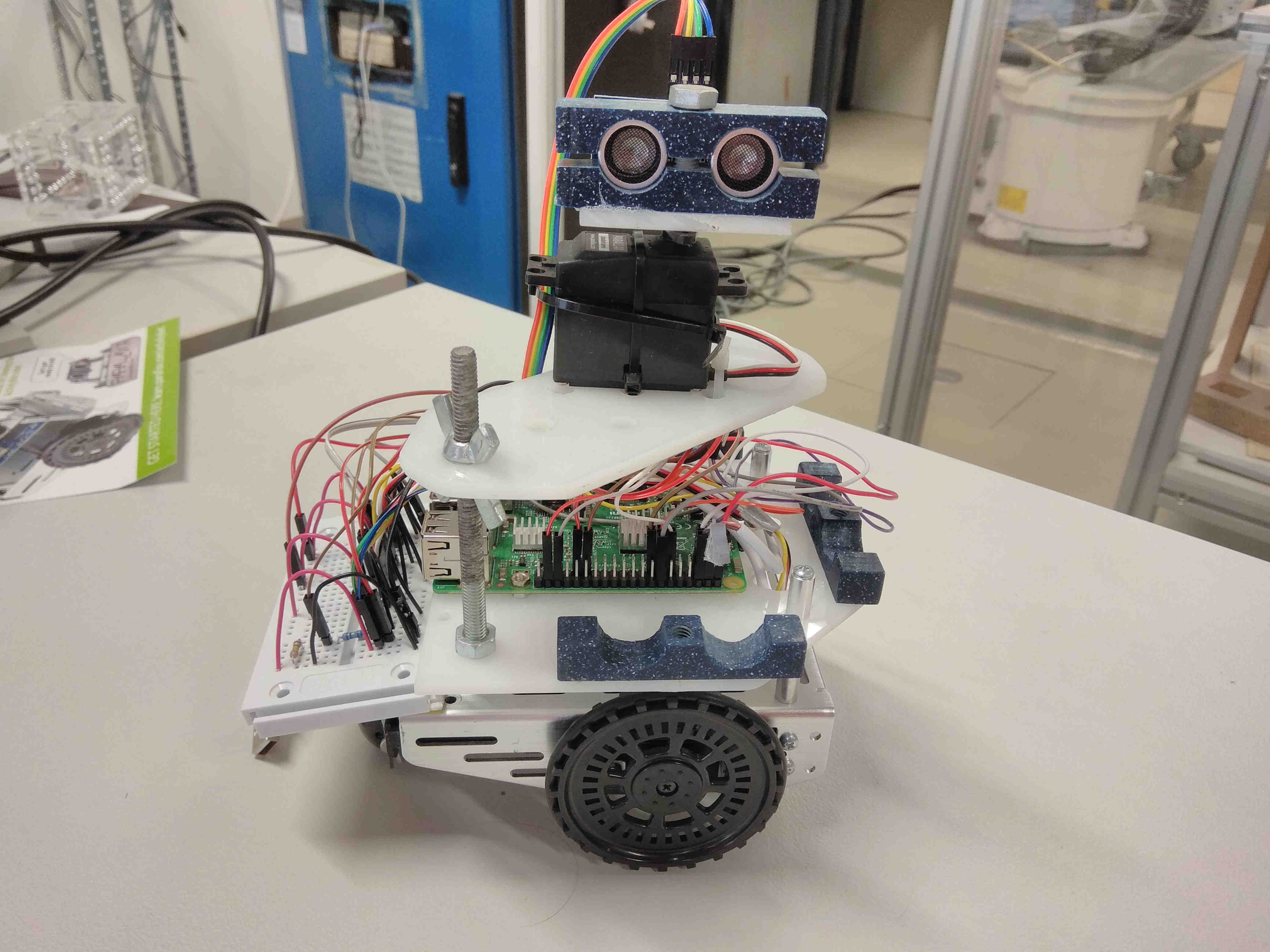
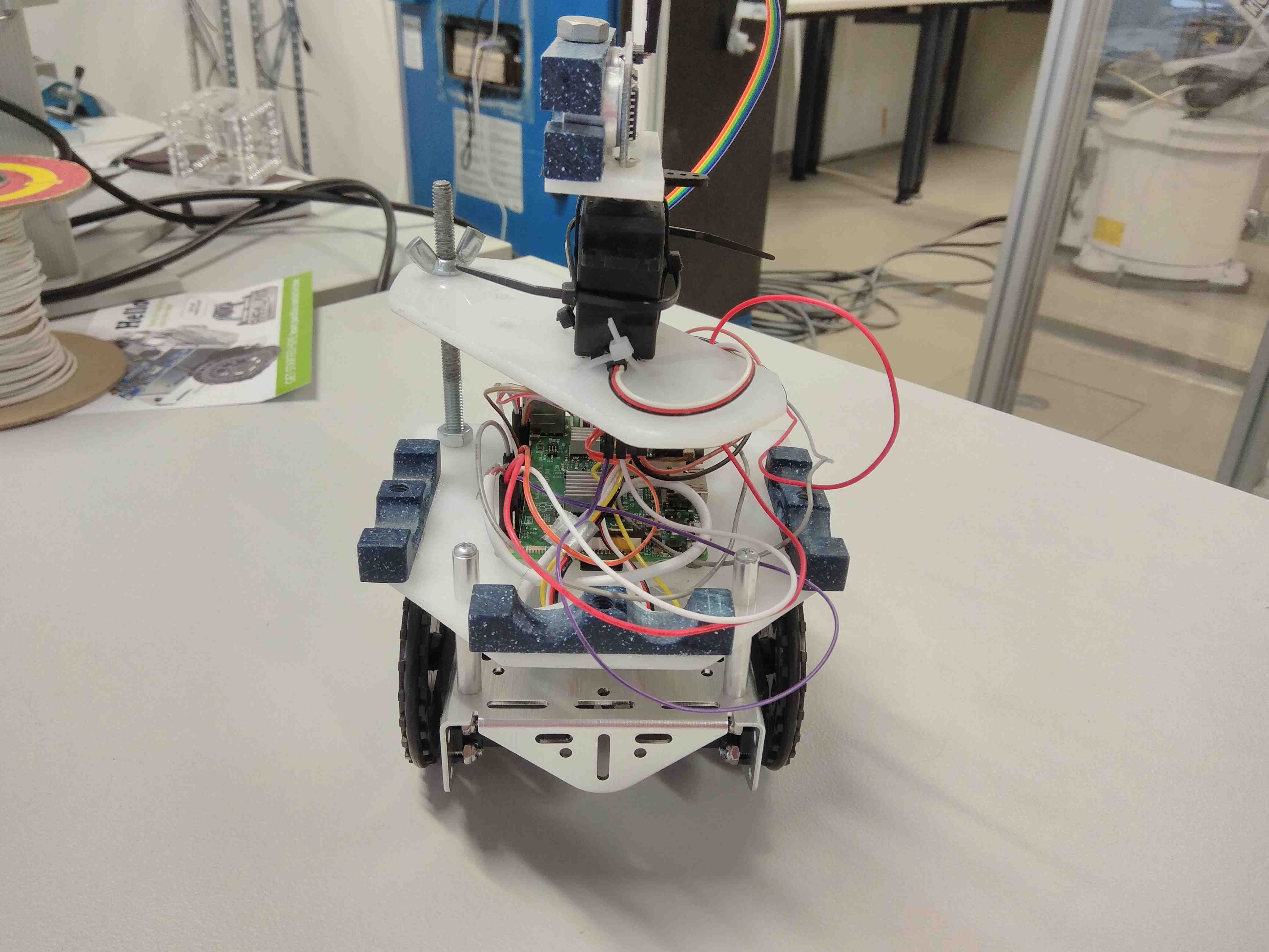
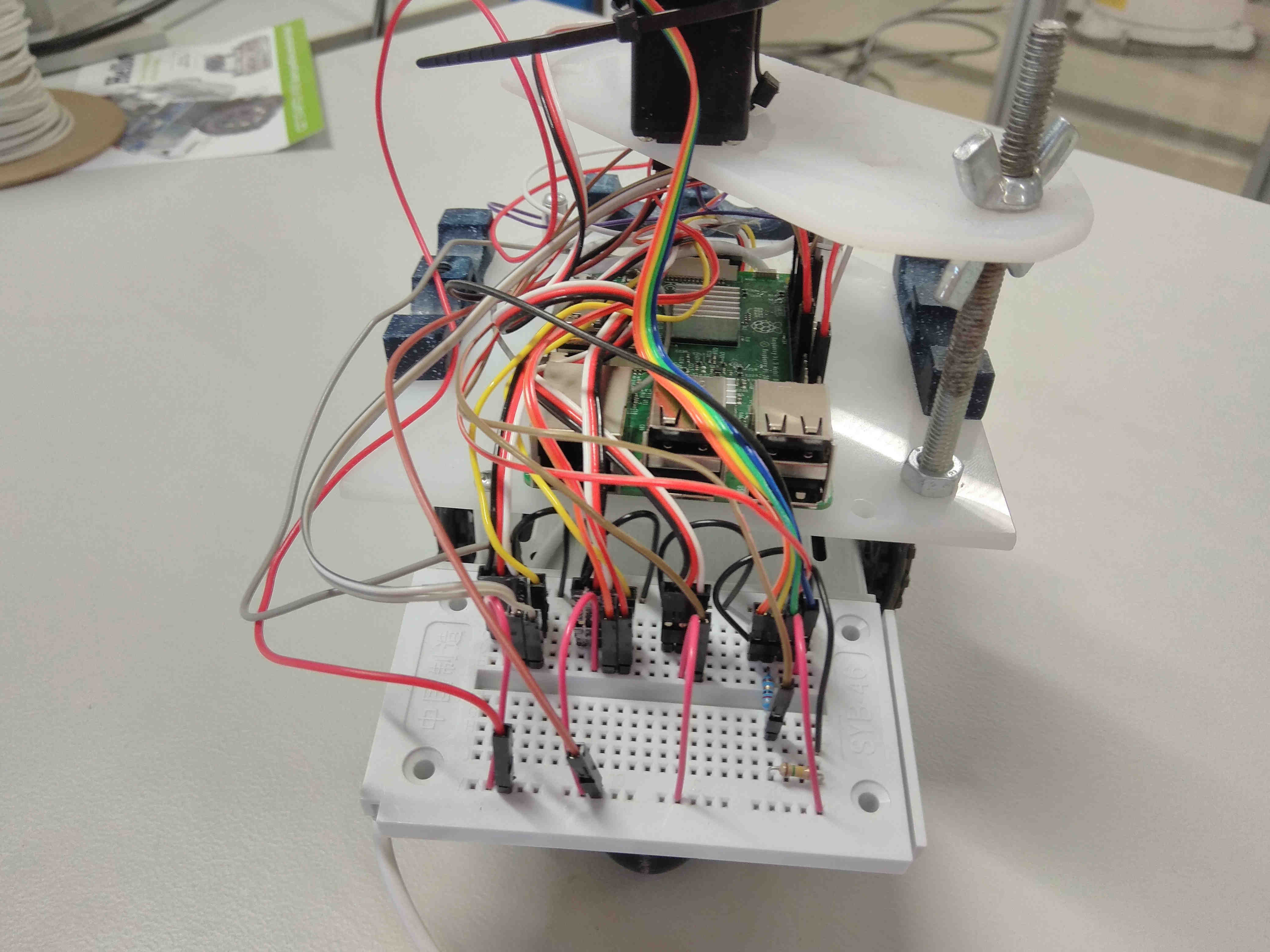
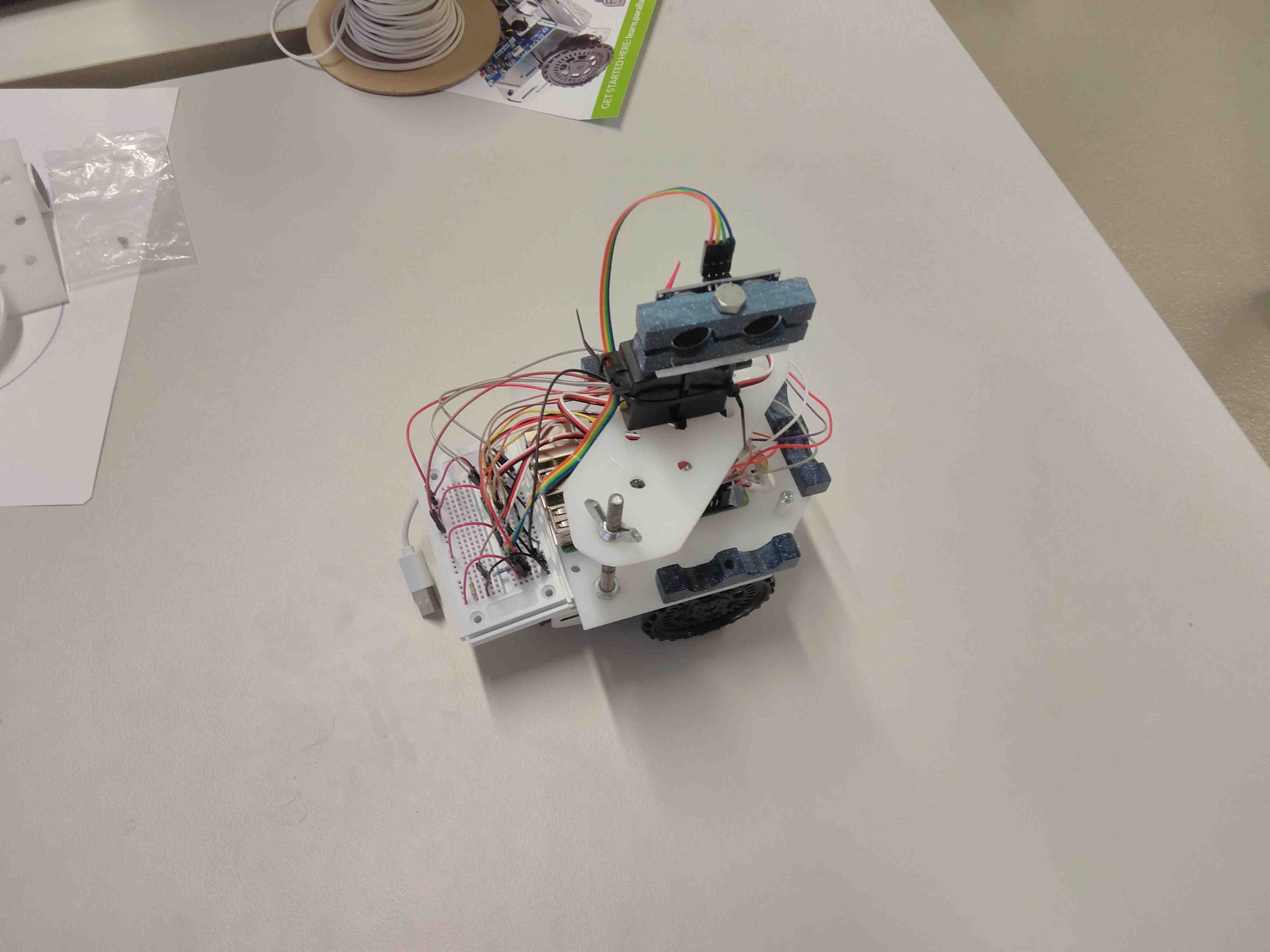
Most of the default values in the modules are those which are used while experimenting/developing with the demo implementation. They provide a good starting point for the range of the values. Pictures of the demo implementation can be found further down in this section.
The modules also enable remote controlling the Raspberry Pis GPIOs. This enables use of the modules on a laptop/computer and over e.g. WLAN remote controlling the Raspberry Pi which provides a WLAN hotspot, see remote_pin [2] and pi_hotspot [1] . So, the robot can freely move with a powerbank attached without any peripheral devices while programming/controlling it. The possibillity of remote controlling the Raspberry Pis GPIOs is a big advantage of the used pigpio [8] module. This drastically improves the use of the modules, because then all programming/controlling can be done on a laptop/computer inlcuding using an IDE, having much more system ressources and so on. It is also possible to use the modules on the Raspberry Pi itself and connect to it over VNC, see VNC [9] . For both ways, using the modules on the Raspberry Pi itself or remote on a laptop/computer to control the Raspberry Pis GPIOs, no modifications have to be done in the source code of the modules.
The documentation is made with Sphinx [10] and can be extended or modified as needed for
e.g. documenting own projects based on this or if extending functionality of the modules
and documenting this. The whole documentation is stored in the docs/ folder.
Instead of buying an ActivityBot 360° Robot Kit 360_kit [3] it is sufficient to buy two Parallax Feedback 360° High-Speed Servos 360_data_sheet [4] , two robot wheels wheel_robot [7], one Parallax Standard Servo stand_data_sheet [5] and a HC-SR04 [6] ultrasonic sensor to build your own chassi/robot.
1.1. Pictures of the demo implementation
View from the right side.
View from the front side.
View from the back side.
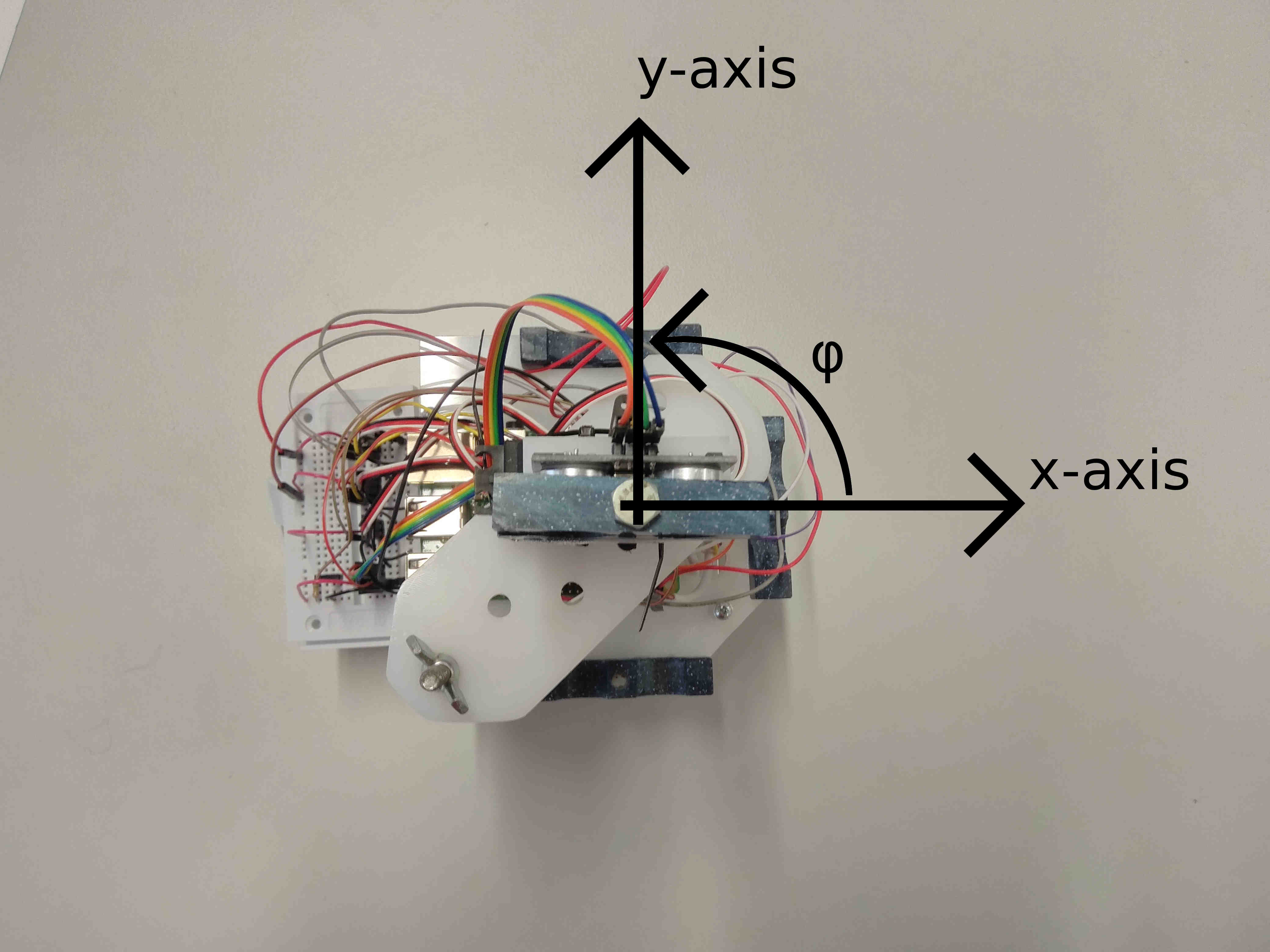
1.2. Used local coordinate system
The following picture shows the local coordinate system which is used in lib_motion .
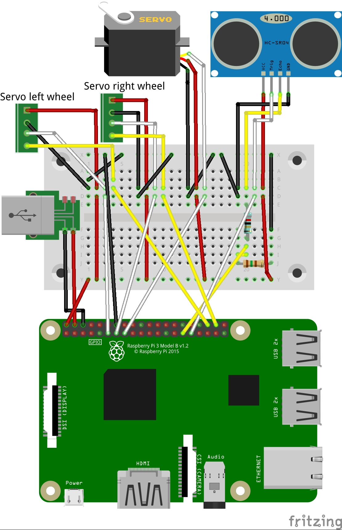
1.3. Cabling of the demo implementation
Below see a Fritzing [11] sheet which illustrates the cabling of the demo implementation. The voltage divider is build out of two resistors, blue one with 82 Ohm and gold one with 150 Ohm.
Warning
The voltage divider is very important. The Echo Pin of the HC-SR04 [6] outputs a
PWM with the same voltage as VCC Pin (5 V in this case) which needs to be converted
to 3.3 V. 3.3 V is the max voltage the Raspberry Pi can handle on a GPIO, otherwise
it might get damaged! The chosen resistors for the voltage divider convert 5 V to
3.23 V. Setup: The output of the Echo Pin is connected to the blue 82 Ohm
resistor. At its end, the GPIO is connected and then the golden 150 Ohm resistor at
whose end ground is connected.
Warning
The 5 V of the USB power supply should be connceted to the 5 V Pin of the Raspberry Pi directly, as shown in the Fritzing sheet. The USB power supply does not only power the Raspberry Pi itself, also the three servos and maybe more devices, which get added in the future, are powered over it. Therefore, powering all devices over the Raspberry Pis micro-USB port should be avoided, because otherwise all needed current of all devices would be conducted through the Raspberry Pi.
1.4. References
| [1] | https://www.raspberrypi.org/documentation/configuration/wireless/access-point.md |
| [2] | http://gpiozero.readthedocs.io/en/stable/remote_gpio.html |
| [3] | (1, 2) https://www.parallax.com/product/32600 |
| [4] | https://www.parallax.com/sites/default/files/downloads/900-00360-Feedback-360-HS-Servo-v1.1.pdf |
| [5] | https://www.parallax.com/sites/default/files/downloads/900-00005-Standard-Servo-Product-Documentation-v2.2.pdf |
| [6] | (1, 2) https://cdn.sparkfun.com/assets/b/3/0/b/a/DGCH-RED_datasheet.pdf |
| [7] | https://www.parallax.com/product/28114 |
| [8] | (1, 2) https://pypi.org/project/pigpio/ |
| [9] | https://www.raspberrypi.org/documentation/remote-access/vnc/ |
| [10] | https://www.sphinx-doc.org/ |
| [11] | http://fritzing.org/ |